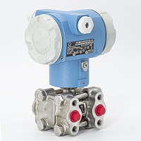
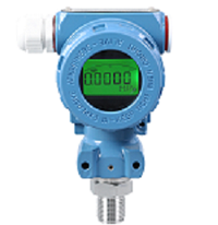
Radar level meter is more common in the level meter, guided wave radar level meter is the star of the radar level meter, it not only looks good, but also has good performance, and high cost performance, so it is very popular, but when it comes to the working principle of guided wave radar level meter, I believe that many people do not understand, including friends who have used it for a long time. So, let's tell you about the working principle of this radar level meter.
Guided wave radar level meter is based on the principle of time domain reflectometry (TDR). The radar level meter based on high frequency oscillator emits electromagnetic pulse, which propagates down the guided wave cable or the guided wave pole. When the surface of the measured medium is encountered, part of the electromagnetic pulse of the radar level meter is reflected back to form an echo. By measuring the running time of the emitted and reflected waves, the formula for calculating the liquid level height is returned to the pulse transmitter t=2d/c along the same path.
Measuring instruments based on the time travel principle are the working principles of guided wave radar level gauges. Radar waves run at the speed of light, and the running time can be converted into a level signal by electronic components. The probe emits a high-frequency pulse that propagates along the cable probe. When the pulse hits the surface of the material, it is reflected back to a receiver in the instrument, which converts the distance signal into a level signal.
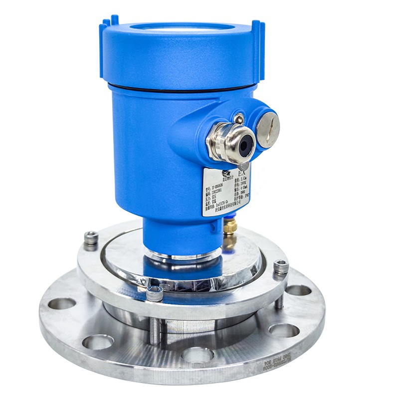
Specifically, the antenna of the guided wave radar sensor emits electromagnetic wave signals in the form of beams, and the emitted waves are reflected on the surface of the measured material, and the reflected echo signals are still received by the antenna. Ultrasonic sampling is used for each point in the transmitted and reflected beams. After being processed by the intelligent processor, the signal gets the distance between the medium and the probe, and is sent to the terminal display for display, alarm, operation, etc.
The relative permittivity of a medium is a physical quantity representing the polarization of the medium, which is determined by the properties of the medium itself. Therefore, different media have different dielectric constants. The reflectivity of the high-frequency pulse signal is directly affected by the reflectivity of the high-frequency pulse signal. When the electromagnetic pulse reaches the surface of the medium, the electromagnetic wave is reflected and refracted.
The larger the relative permittivity, the smaller the reflection loss, and the smaller the relative permittivity, the greater the emission loss and the more serious the signal attenuation. If the conductivity of the measured medium is greater than 10mS/cm, it will all be reflected back, and the stronger the wave signal is. An excessively small relative permittivity will result in extreme attenuation of the signal. Therefore, each guided wave radar level gauge has a minimum relative dielectric constant to ensure the normal use of the radar level gauge. Different companies have different structural designs for guided wave radar level gauges, and have different requirements for the minimum relative permittivity.
Guided wave radar liquid level meter signal energy is small, can provide a fast and efficient channel from signal to liquid transmission, signal attenuation is kept to a minimum, so can be used to measure the medium level of the medium constant is very low; In addition, due to the small energy consumption of the guided wave radar, the power supply circuit is not a separate AC power supply, which greatly saves the installation cost.
Contact:

Chat Online

