Products
Contact Us
Get A Quote
Recommend
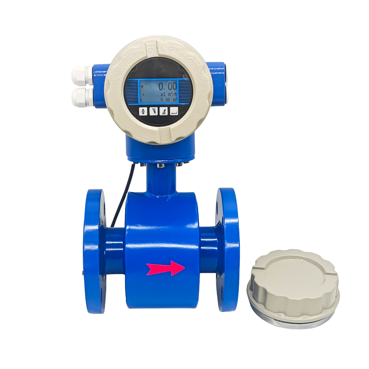
We pay our attention to every detail in the process of the product structure design, material selection, manufacturing, assembly and factory testing etc. With a water tower up to 37m as pressure stabilizer for actual flow calibration, we have a professional production line for electromagnetic flowmeter, also we design and develop a series of software and hardware for electromagnetic flowmeter for mass production to ensure high quality in long term use . It can be widely used in the measurement of central heating, heating, air conditioning and other heat in civil residential quarters, office buildings and enterprises andinstitutions.
Product Description
Description
Product Composition
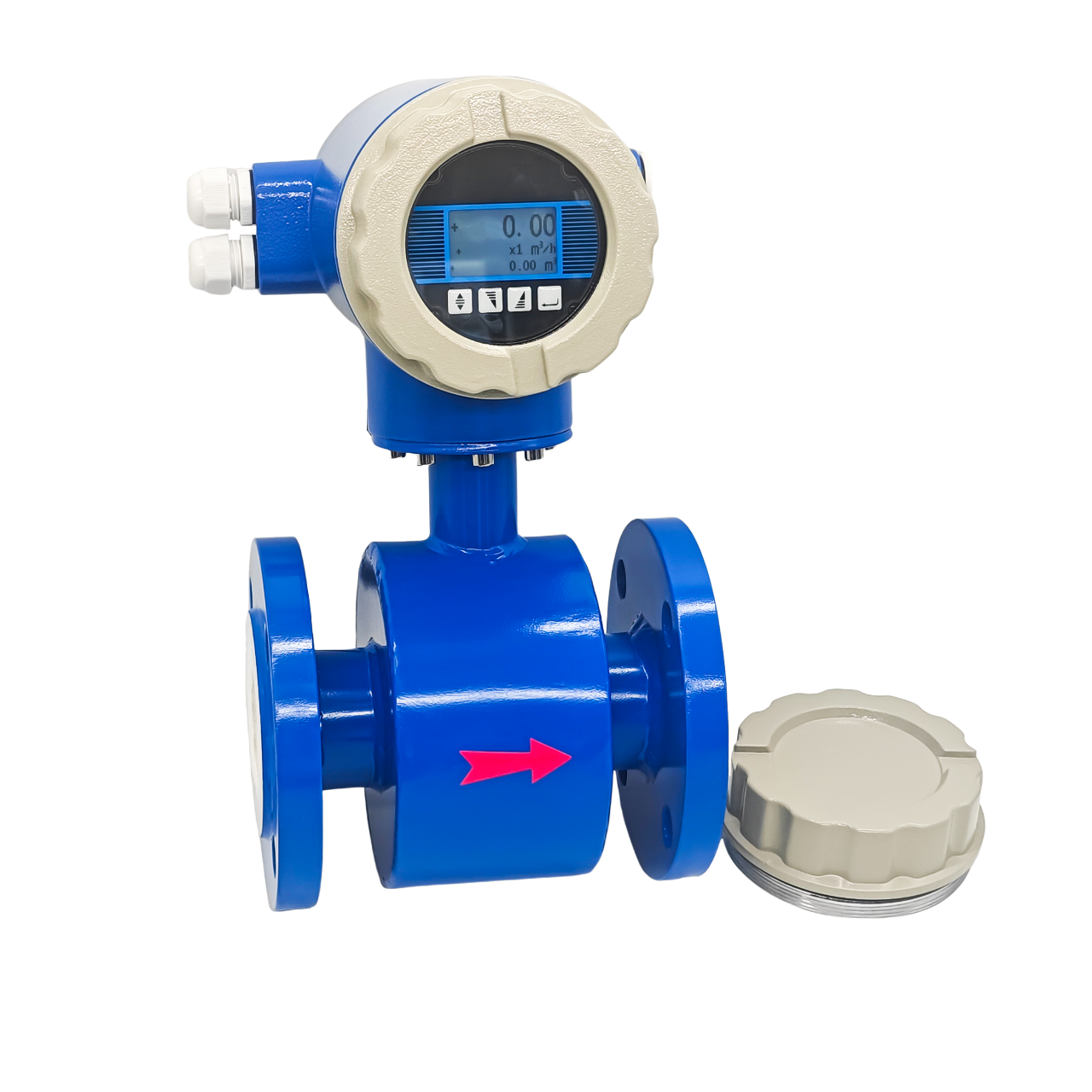
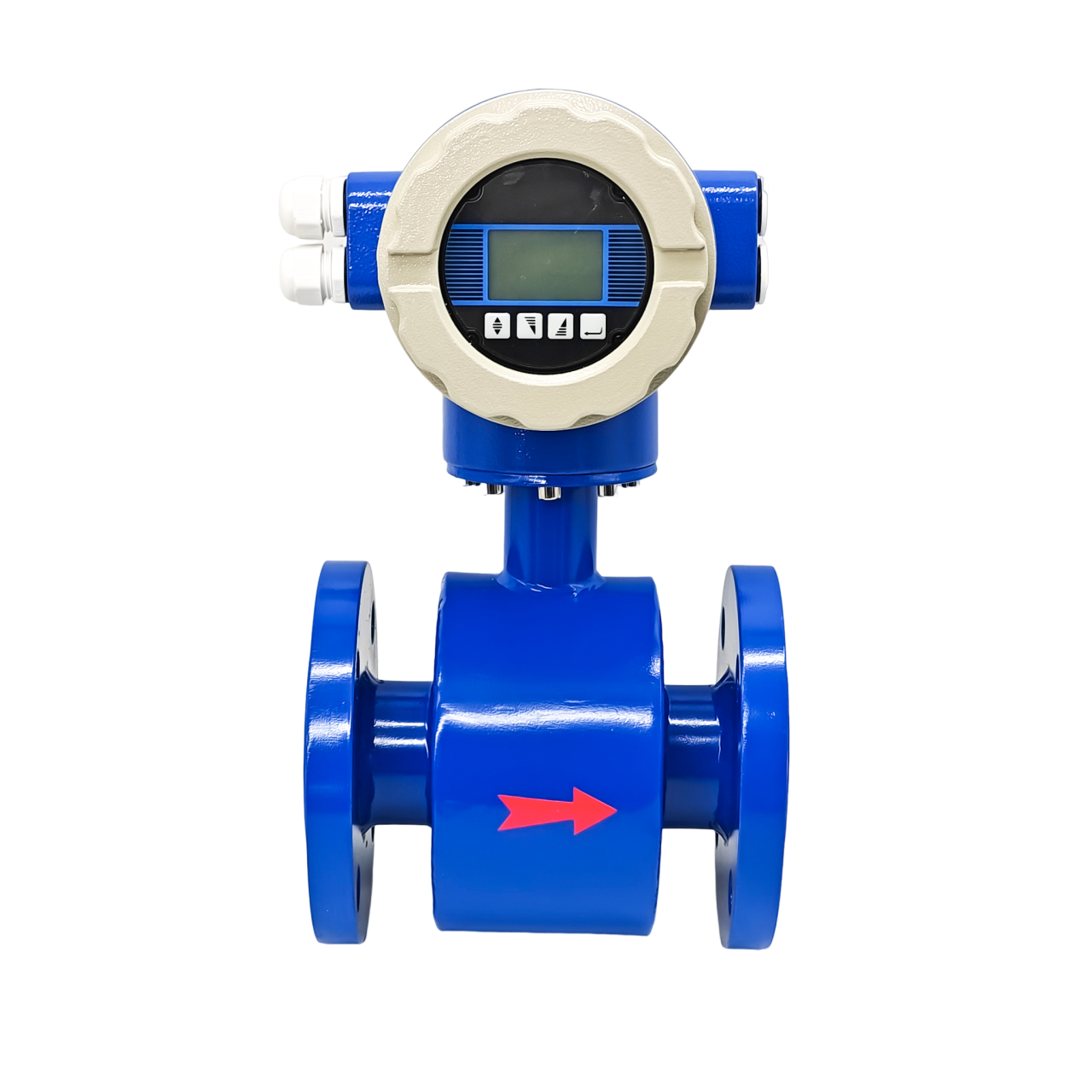
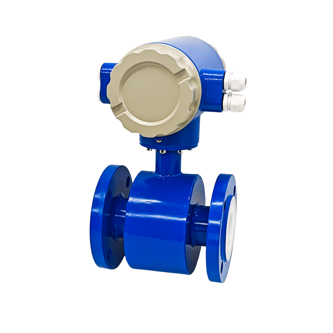
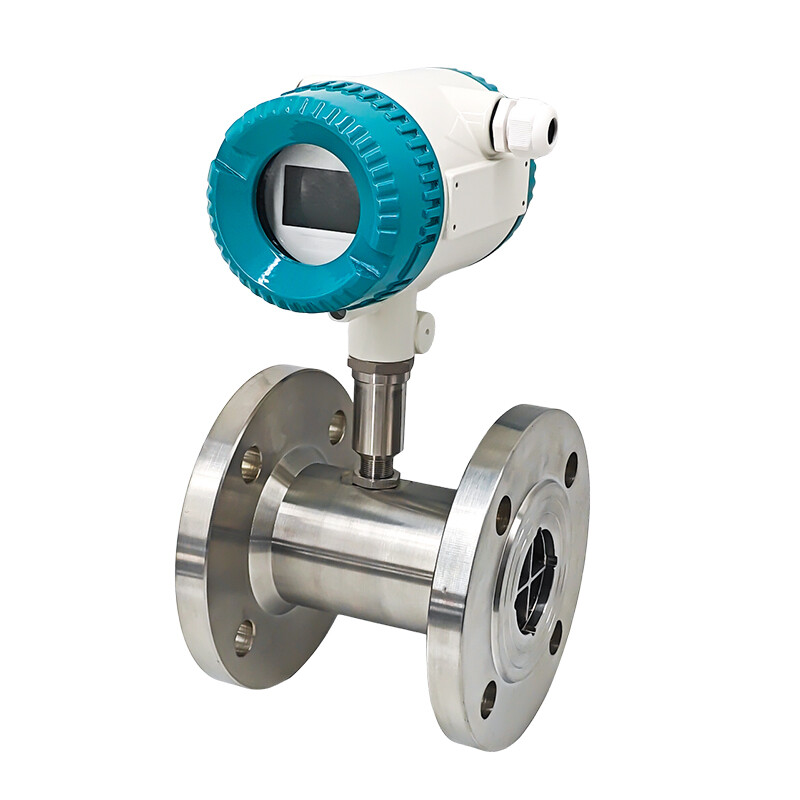
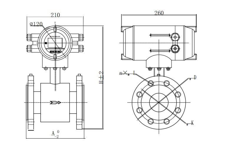
The electromagnetic flowmeter is composed of two parts: the electromagnetic flow converter and the electromagnetic flow sensor. The separate type also needs two dedicated double-layer shielded cables to connect the converter and the sensor.
Product type
The series of electromagnetic flow meters are divided into two structural forms: integrated type and separate type. It can be used in specified explosion-proof places.
The sensor is available in 7 different materials for the electrodes and 4 different materials for the lining.
Parameter
Detail
Feature
• The energy meter has the function of measuring cold and heat, and is equipped with 2 Pt1000 as standard, no additional totalizer is required, which is convenient for installation and reduces installation costs;
• The converter uses a low-power single-chip microcomputer to process data, adopts SMD electronic components and surface mount SMT technology, and has reliable performance, high precision, low power consumption and stable zero point;
• Adopt multi-electrode structure, high accuracy, equipped with ground electrode, no need for ground ring, cost saving;
• Multi-electrode structure ensures high accuracy. With the grounding electrode, it doesn't need grounding ring which saves the cost;
• When power off , EEPROM can protect parameter setting and cumulative values;
• The electromagnetic energy meter has no mechanical inertia, has a sensitive response, can measure instantaneous pulsating flow, and hasgood linearity;
• Low frequency rectangular wave excitation improves flow stability, low power loss and excellent low flow rate characteristics.
Working Principle
The working principle of Electromagnetic Flowmeter is based on Faraday's Law of Electromagnetic Induction, that is, when the conductive liquid flows through the electromagnetic flowmeter, the induced electromotive force will be produced in the liquid conductor, and the induced electromotive force is directly proportional to the velocity of conductive liquid, magnetic flux density and width of conductor (interior diameter of flowmeter). Such induced electromotive force is detected by a pair of electrodes on the tube wall of the flowmeter, and the equation of induced electromotive force is as follows:
U = K×B×V×D
U: Induced electromotive force
K: Instrument Constant
B: Magnetic flux density
V: Velocity
D: Interior diameter
of measuring pipe
Contact

Message
Products Recommended
Chat Online

